A Practical Guide to Implementing Redundant DC Power Systems Using Dedicated Decoupling Modules
Introduction
In DC-powered systems, redundancy is often specified but not always implemented correctly. A common approach is to parallel two power supplies and assume the system is protected. In practice, without proper decoupling, this creates risks including backfeed between supplies, uneven load distribution, and unpredictable behaviour during a supply fault.
A dedicated redundancy module resolves this by electrically isolating each source while maintaining a continuous output to the load.
The Camtec RED00202 (R2) provides a structured and predictable method of implementing N+1 redundancy in DC systems up to 1,000W, without introducing unnecessary complexity into the design.
Simple and Predictable Implementation
One of the key advantages of the RED00202 (R2) is how straightforward it is to implement.
From a wiring perspective:
- Two independent DC power supplies
- One redundancy module
- One combined DC output to the load
There is no requirement for configuration, communication, or control logic. The module operates using Schottky barrier decoupling diodes, providing deterministic behaviour that is easy to design around.
For panel builders and system integrators, this reduces design time, simplifies commissioning, and allows redundancy to be added to existing systems with minimal rework.

True Multi-Voltage Coverage: 24Vdc, 48Vdc and 110Vdc
Most redundancy solutions in the market are focused on 24Vdc industrial automation systems.
The Camtec RED00202 (R2) series includes models suitable for all common industrial DC voltages, including 24Vdc, 48Vdc, and 110Vdc systems.
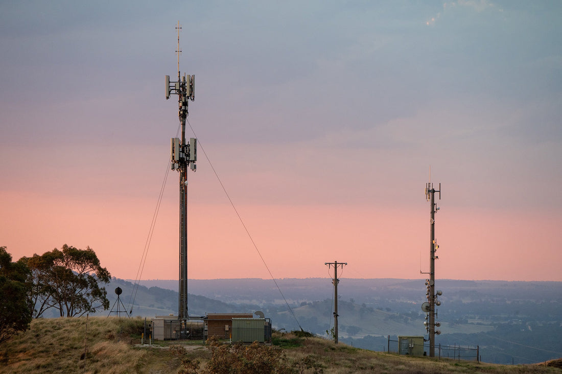
This makes it particularly relevant for:
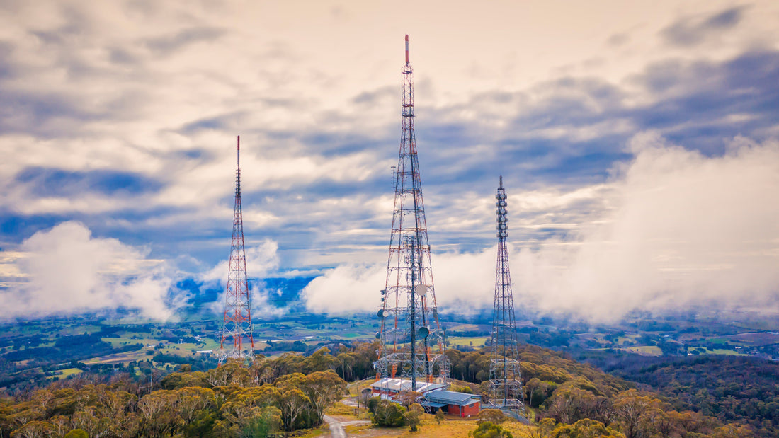
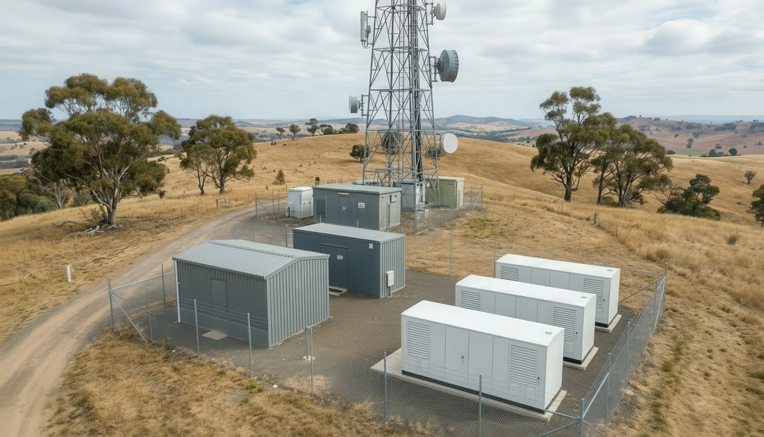
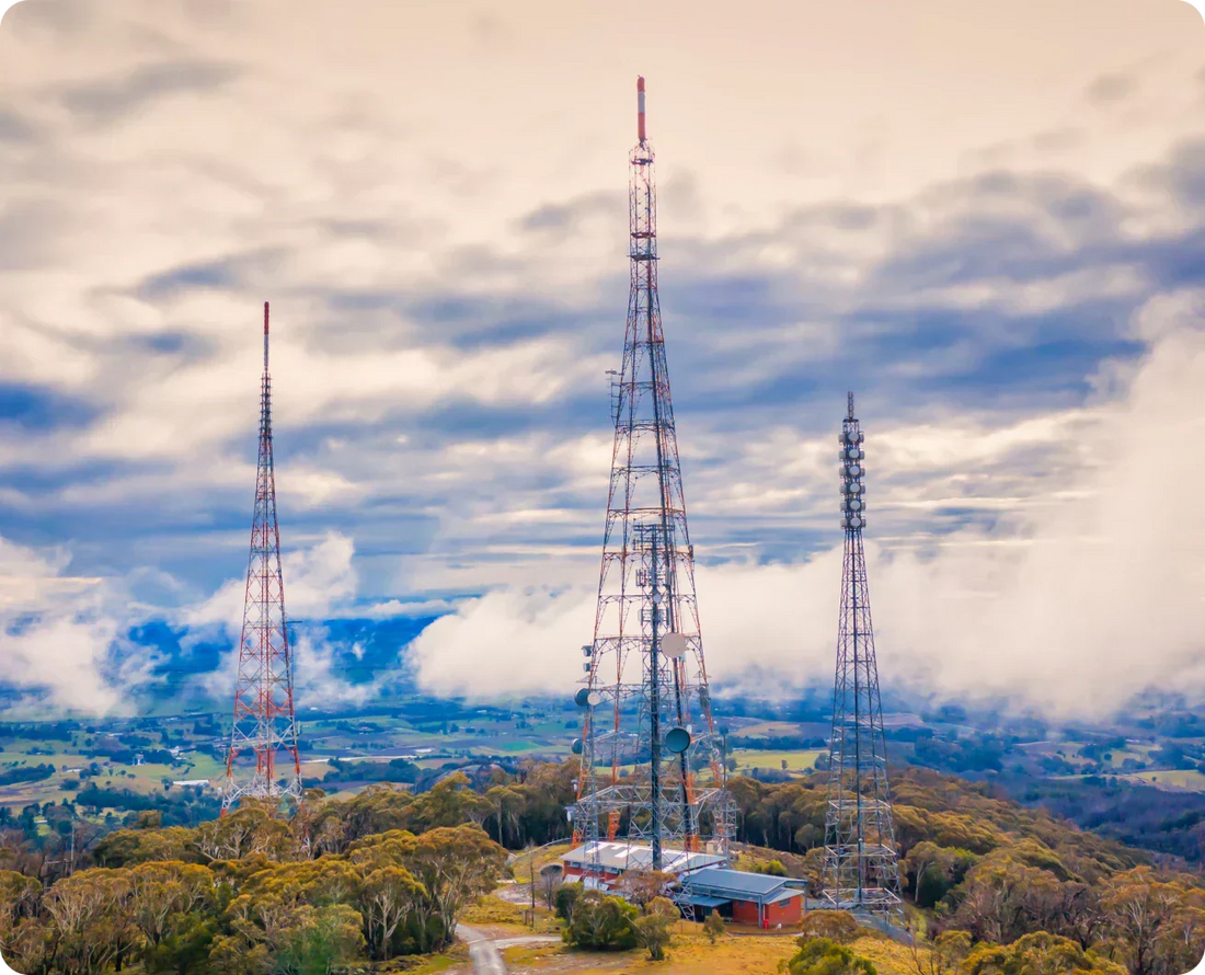
- Telecommunications systems operating at 48Vdc
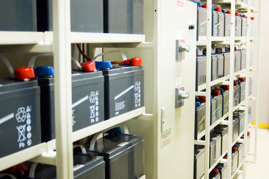
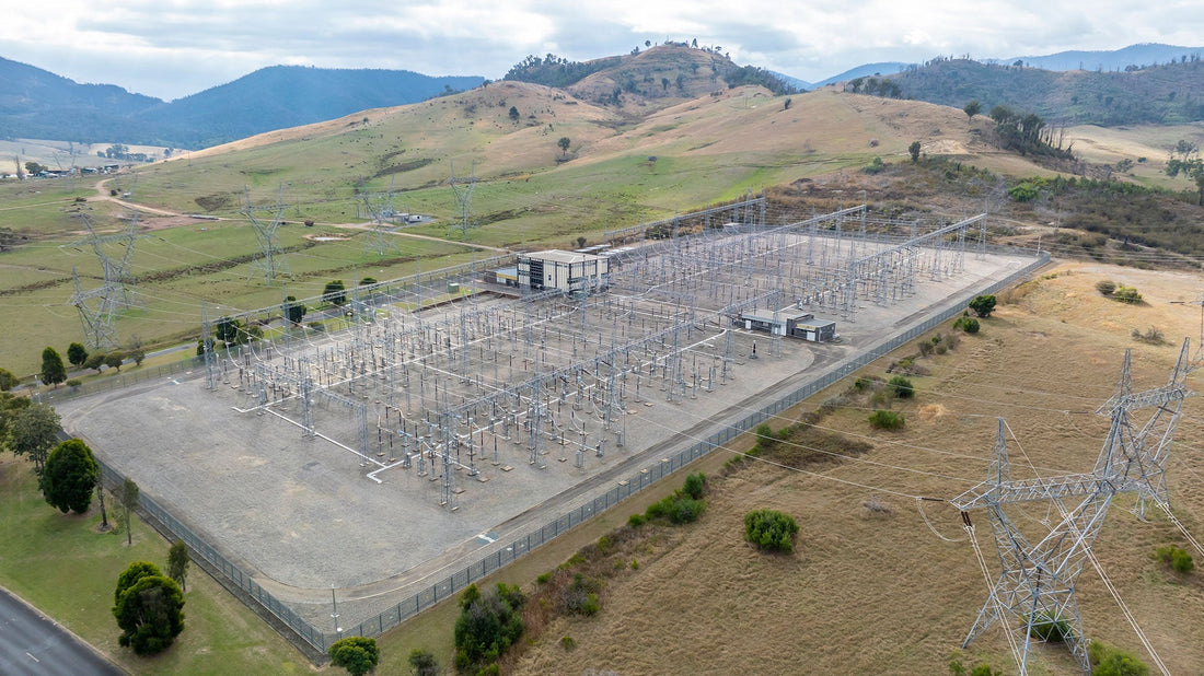
- Industrial and utility applications requiring 110Vdc
Using a common product family across these voltage platforms enables a consistent design and installation approach, reducing engineering effort and simplifying long-term support across mixed-voltage sites.

Managing Voltage Drop in Redundant DC Architectures
In diode-based redundancy, voltage drop must be accounted for as part of the system design.
Typical values for the RED00202 (R2):
- ~500mV in 24V systems
- ~600mV in 48V systems
- ~700mV in 110Vdc systems
These values allow engineers to accurately calculate delivered voltage at the load, validate operating margins, and avoid undervoltage issues during peak demand.
The objective is not to eliminate voltage drop, but to ensure it is known, consistent, and designed into the system.
Redundancy Does Not Equal Load Sharing
It is important to distinguish between redundancy and load sharing.
The RED00202 (R2), like other diode-based OR-ing solutions, provides effective decoupling between power supplies, ensuring uninterrupted operation if one source fails. However, it does not enforce equal load sharing.
In practice:
- The power supply with the slightly higher output voltage carries most of the load
- The second supply remains in standby until required
In systems using high-quality power supplies with tight output voltage regulation, some degree of natural load sharing can occur due to closely matched output characteristics. This can improve utilisation compared to loosely regulated supplies, particularly in lower current or well-controlled environments.
However, this behaviour is not controlled or guaranteed. For applications where equal load sharing, balanced thermal loading, or maximum utilisation of both power supplies is required, power supplies with active current sharing functionality should be specified.
For most industrial and infrastructure systems, standby redundancy is sufficient when correctly sized and monitored.

External Redundancy Module vs Built-In Diode?
Some power supplies include internal decoupling diodes, which can give the impression that a separate redundancy module is unnecessary. In practice, there are clear differences.
| Feature | Internal Diode (PSU) | RED00202 (R2) Module | Active Current Sharing |
| Decoupling method | Schottky (internal) | Schottky diodes (external module) | MOSFET with controlled current sharing |
| Fault isolation | Limited to PSU | External and independent | External and controlled |
| Voltage drop visibility | Often unclear | Defined and specified | Very low |
| Monitoring | Typically none | Relay output included | Often integrated |
| Load sharing behaviour | Uncontrolled | Uncontrolled | Controlled |
| Complexity | Low | Low | Higher |
Using a dedicated module separates redundancy from the power supply, making it a defined and visible part of the system design rather than an assumed internal feature.
Compatibility with Power Supplies
The RED00202 (R2) can be used with any suitable DC power supply, provided voltage and current ratings are correctly matched.
However, performance improves when used with matched, tightly regulated power supplies, where output tolerances are controlled.
In practice, pairing with Camtec’s industrial precision power supplies offers advantages:
- Improved predictability of load distribution
- Stable output voltage alignment between units
- Consistent behaviour across installations
This is particularly relevant in higher current systems or distributed infrastructure where small voltage variations can influence system performance.
Built-in Monitoring Improves Fault Visibility
Basic redundancy implementations often provide no indication of system health. A failed power supply can remain undetected until a second failure occurs.
The RED00202 (R2) includes a power-good relay with changeover contact, triggered by:
- Undervoltage conditions (adjustable threshold)
- Overvoltage conditions (factory set)
This enables integration into PLCs, alarms, or remote monitoring systems, allowing early detection of faults and proactive maintenance.
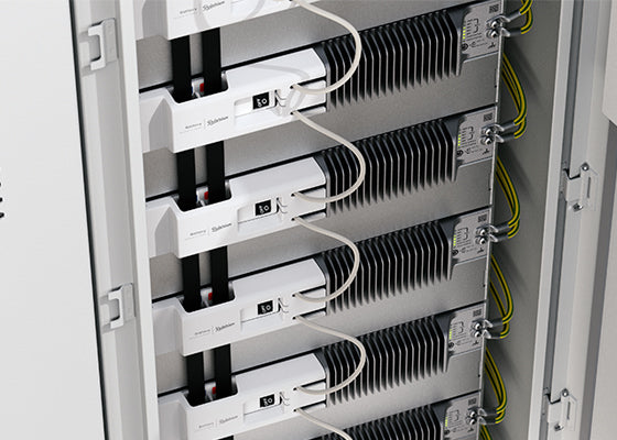
Designed for Real-World Panel Integration
The module is engineered for practical deployment:
- DIN rail mounting
- Natural convection cooling
- Operating temperature from -20°C to +70°C
- Compact footprint for standard control panels
Correct installation remains important. Vertical mounting and appropriate airflow clearance ensure reliable thermal performance over time.
Frequently Asked Questions
What does a DC redundancy module do?
A DC redundancy module decouples two independent power supplies and combines them into a single output, ensuring that if one supply fails, the other continues to power the load without interruption.
Does a redundancy module provide load sharing between power supplies?
No. The RED00202 (R2) does not enforce load sharing. The power supply with the slightly higher output voltage will typically carry the load, while the second supply remains in standby.
What is the difference between an internal diode fitted to a power supply’s output and an external redundancy module?
An internal diode is built into the power supply, while an external module provides independent decoupling, defined performance, monitoring capability, and greater flexibility in system design.
Why is voltage drop important in redundancy modules?
Voltage drop reduces the voltage delivered to the load. This must be accounted for to ensure connected equipment operates within its specified range, particularly under peak load conditions.
Can the RED00202 (R2) be used with any power supply?
Yes, provided voltage and current ratings are matched. Best results are achieved with tightly regulated, matched power supplies such as Camtec’s industrial precision range.
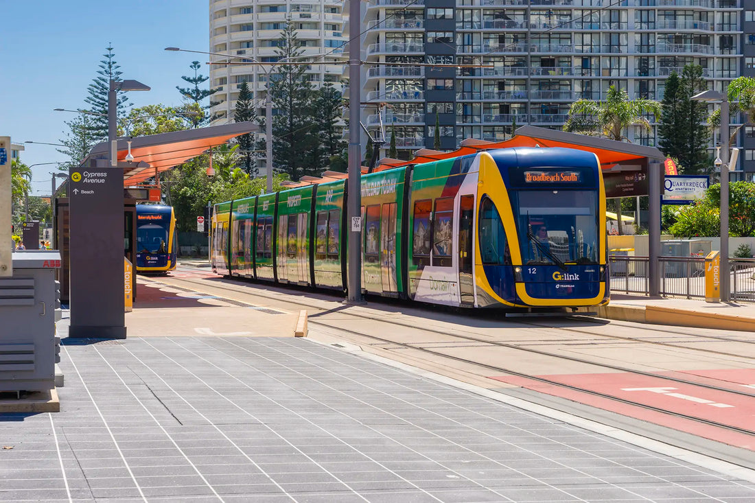
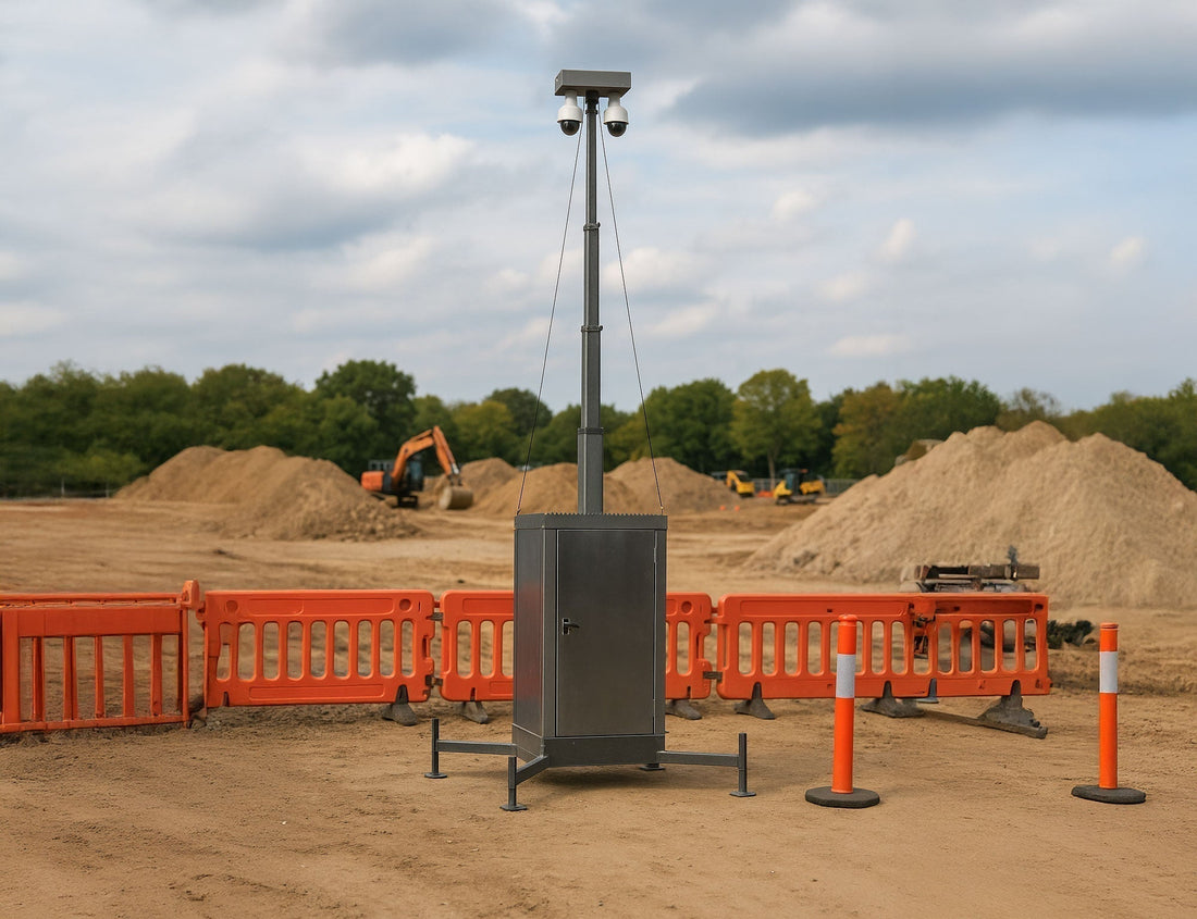
What applications typically require a redundancy module?
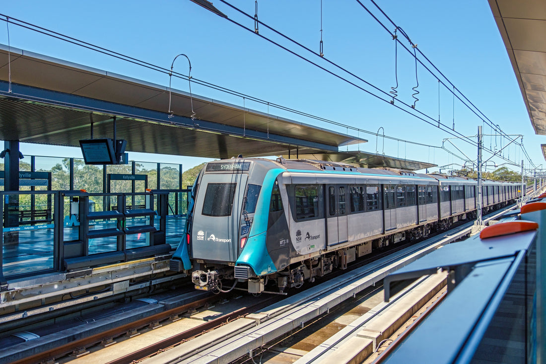
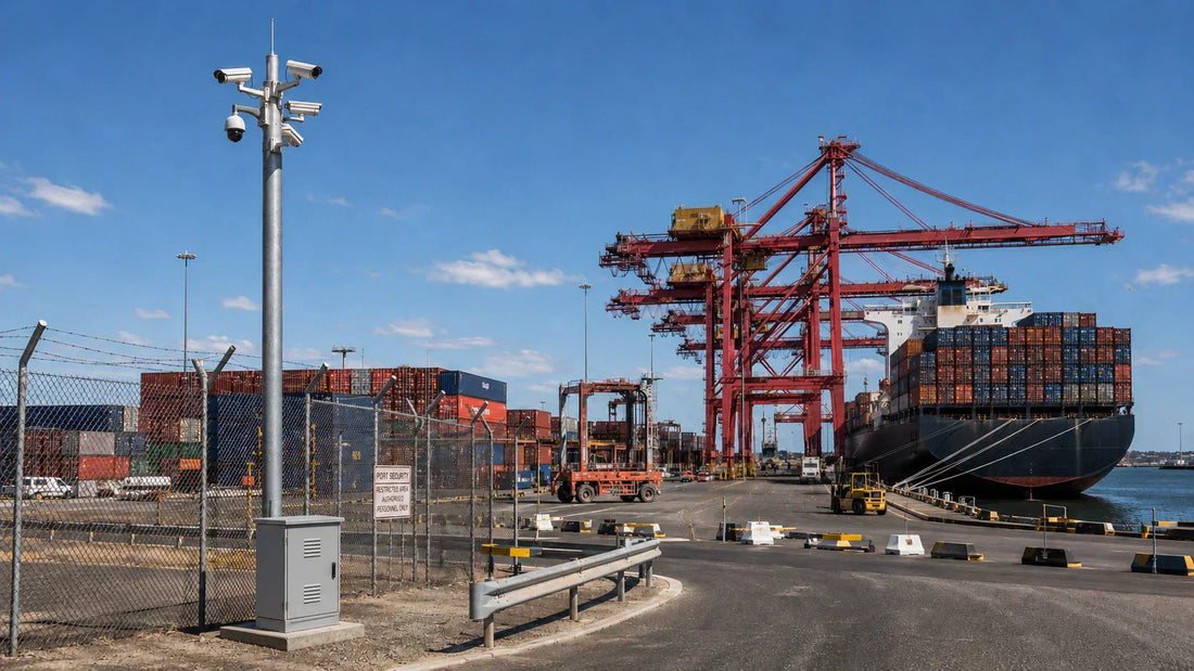
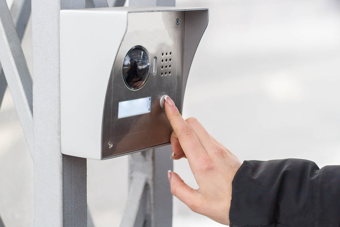
Applications include industrial automation, telecommunications, security systems, and utility or rail infrastructure where continuous DC power is required.
Does the RED00202 (R2) provide monitoring?
Yes. It includes a power-good relay that can be integrated into monitoring or alarm systems to detect supply faults.
Is the RED00202 (R2) difficult to install?
No. It is DIN rail mounted and requires only two DC inputs and one DC output, with no configuration required.
Ordering Information
| Model | Voltage Range | Max Input Current | Max Output Current | Vdrop (typ.) |
| RED00202A(R2) | 0 to +28 Vdc | 2 x 50 A (2 x 1000 W) | 50 A (1000 W) | 500 mV |
| RED00202B(R2) | +36 to +60 Vdc | 2 x 28 A (2 x 1000 W) | 28 A (1000 W) | 600 mV |
| RED00202C(R2) | +90 to +125 Vdc | 2 x 9.1 A (2 x 1000 W) | 9.1 A (1000 W) | 700 mV |
Final Thoughts
Redundancy in DC systems is not achieved by simply adding a second power supply. It requires controlled decoupling, predictable electrical behaviour, and visibility of system health.
The Camtec RED00202 (R2) delivers this through:
- Simple, deterministic diode-based operation
- Straightforward integration into new or existing systems
- Coverage across 24Vdc, 48Vdc and 110Vdc architectures
- Defined voltage drop characteristics
- Integrated monitoring for fault detection
- 1,000W redundancy capability
At Powerbox Australia, we do more than supply components. We support engineers with system design, model selection, and integration to ensure reliable redundant DC power systems across industrial, telecommunications, and utility applications. We also stock a range of RED00202 models to support common 24Vdc, 48Vdc, and 110Vdc system requirements.
About the Author
James Rutty is a Director at Powerbox Australia, bringing over 15 years of experience supporting industry across Australia and New Zealand. He works closely with the Powerbox team to ensure integrators, consultants, distributors and end users are equipped with correctly specified, standards-compliant DC power systems that deliver reliable performance in the field.