Powerbox PB315 SERIES DC/DC Converter - Railway (500W)
The Powerbox PB315 Series DC/DC Converter is a powerful and reliable 500W solution designed specifically for railway applications. Complying with EN50155 and EN50121-3-2 standards, it provides clean and stable 24Vdc power for critical onboard systems, signaling, and other rail-specific needs. Key features include a wide input voltage range (45-1...
Read MoreThe Powerbox PB315 Series DC/DC Converter is a powerful and reliable 500W solution designed specifically for railway applications. Complying with EN50155 and EN50121-3-2 standards, it provides clean and stable 24Vdc power for critical onboard systems, signaling, and other rail-specific needs.
Key features include a wide input voltage range (45-154Vdc) supporting 72V, 96V, and 110Vdc systems, high efficiency (90%), and robust protections such as input reverse polarity, inrush current limiting, and overvoltage lockout. Its rugged, IP40-rated chassis mount enclosure is built to withstand harsh environments, withstanding vibration, shock, and wide temperature ranges (-30°C to 70°C with derating).
The PB315 Series offers 500W continuous power with natural convection cooling, eliminating the need for additional fans or cold plates. The integrated redundancy diode supports parallel operation for increased reliability, and the modular design ensures easy integration with flexible input and output connection options.
The Powerbox PB315 Series is the ideal choice for demanding railway applications requiring reliable, high-performance DC/DC power conversion.
Show Less
Features
- 250W and 500W DC/DC converters for railway
- 45-154Vdc input to supply 24Vdc 20.8A or 10.4A
- Natural convection cooling with integral heatsink
- High resistance to pollution
- Wide input voltage range
- High efficiency low thermal stress
- Different input/output connectors
- Input polarity reversal protection
- High tolerance of input ripple
- Input inrush current limiting
- Input overvoltage lockout
- Output overload protection
- Output overvoltage protection
Specifications
| INPUT | |
|---|---|
| Input voltage | 45-154Vdc Complies with power supplied from an accumulator battery with the nominal voltage of 72Vdc, 96Vdc, or 110Vdc as per EN50155:1996 |
| Input current | 15A |
| Inrush Current | 25A at 110Vdc input |
| DC ripple factor | 15% (EN50155 cl. 3.1.1.4) |
| PROTECTION | |
|---|---|
| Input reverse polarity | Indefinite, series diode on input. |
| Input fusing | 15A, 500V (T) HRC ceramic 32 x 6.3mm fuse - internal |
| Input overvoltage (Shutdown) | Approx 160Vdc, Auto recovery. |
| High input ripple | Indefinite. Series diode on input. |
| Output short circuit | PB315-24*-H: 24Vdc 33A PB315-24*: 12Vdc 16.5A Indefinite. Auto recovery |
| Output overcurrent (Current limit) | PB315-24*-H: 24Vdc 31A PB315-24*: 12Vdc 15.5A Auto recovery on removal of over current |
| Output overvoltage (shutdown) | 30-35Vdc Input power must be cycled off then on to restart |
| Over temperature | 110C internal temperature. Auto restart after cooling down |
| OUTPUT | |
|---|---|
| Output Voltage | 24Vdc (23.76 - 24.24V) |
| Output Current | PB315-24*-H: 20.8A PB315-24*: 10.4A |
| Continuous power | PB315-24*-H: 500W PB315-24*: 250W See derating curve |
| Ripple voltage | 100mV p-p |
| Line regulation | 0.5% at full load |
| Load regulation | 1.13Typ (1.0-1.5) %Vnom. 0% to full load measured before redundancy diode |
| Efficiency | 90% at full load |
| Power dissipated | PB315-24*-H: 55W at full load PB315-24*: 27.5W |
| Redundancy diode | 0.33 (0.2 - 0.7) Vdc |
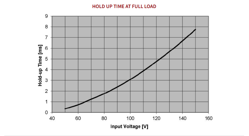
| Hold up time | See technical illustration |
| ISOLATION | |
|---|---|
| Isolation | Input to Chassis: 2121Vdc Input to Output: 4242Vdc Input to Output (M input connector): 3960Vdc Output to Chassis: 707Vdc |
| Rated Insulation voltage | Input: 154Vdc Output: 25Vdc per IEC60077-1 |
| Rated Impulse withstand voltage | Input: 2.5KV Output: 0.8KV per IEC60077-1 |
| Overvoltage Category | Input and Output: OV2 per IEC60077-1 |
| ENVIRONMENT | |
|---|---|
| Operating Ambient Temperature | See technical illustrations |
| Cooling | Natural convection No cold plate required |
| Relative Humidity | 5% - 90% Non condensing |
| Degree of Pollution | PD3 (Per IEC60077-1) |
| I/O INTERFACE | |
|---|---|
| Input Output Terminal Code: * | PB315-24 * (-H) |
| Input and Output: S | 5 way screw T/B 40A/600V suitable for M4 ring lugs. |
| Input and Output: C | 7 way cage clamp T/B 20A/300V suitable for 4mm2 wire |
| Input and Output: F | 10 way 6.4mm male QC faston terminals |
| Input and Output: P | Phoenix contact pn DFK-PC-15/5-STF-10,16 or similar 5W feed through terminal block with screw flanges Mating connector: Phoenix contact pn PC 6/5-STF-10,16 or equivalent 5W pluggable screw terminal block with screw flanges suitable for 6mm2 wire supplied with unit. |
| Input and Output: M | MS3102E24-22P F80 panel mounted plug. 4 x #8AWG crimp contacts. MS service rating D Mating connector: MS3106E24-22S F80 straight receptacle, supplied with unit. |
| Ground Terminal | M5 x 12mm stud |
| "ON" LED | Option L: Green LED mounted on top cover. ON when output voltage is present |
| ELECTROMAGNETIC COMPATIBILITY | |
|---|---|
| General | Designed to comply with EN50121-3-2:2000 and EN50155:1996 |
| Conducted Emissions (Input and Output) | 150kHz-500kHz: 99dBuV QP 500kHz-30MHz: 93dBuV QP |
| Radiated Emissions | 30MHz-230MHz: 40dBuV/m QP @ 10m 230MHz-1HHz: 47dBuV/m QP @ 10m |
| Fast Transient Burst Immunity | 2KV 5/50nS Tr/Th 5KHz rep frequency |
| Surge Immunity | Input only per EN50155 Direct Transients 1.8KV waveform 5/50us Source impedance 100ohm |
| Conducted Radio Frequency Immunity | 3Vrms carrier 150KHz to 80MHz 1KHz , 80% AM Source impedance 150 ohm |
| Variations & Interruptions of voltage supply | Input only per EN50155 Unit complies with 45Vdc to 154Vdc (0.6 x 72V to 1.4 x 110V) operation continously Class S1: No interruptions |
| Radio Frequency Immunity | 10V/Mrms carrier 80MHz to 1 GHz 1KHz 80% AM |
| Electrostatic Discharge | 6KV contact discharge 8KV air discharge |
| MECHANICAL | |
|---|---|
| General | Chassis mount enclosure suitable for standalone use |
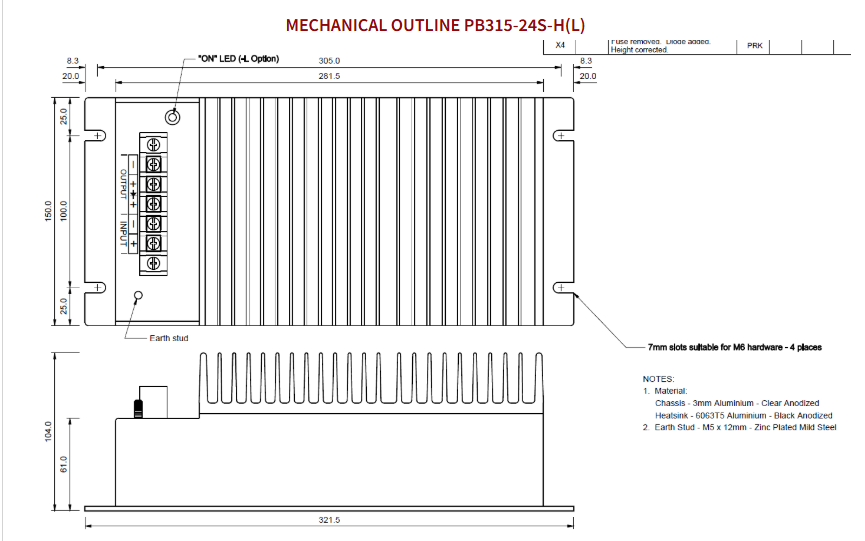
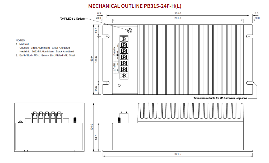
| Mechanical Outline | L: 321.5L, W: 150mm H: S=86, F=87, H=104mm (without mating connector) |
| Mounting Centres | 305mm x 100mm Suitable for 4 x M6 hardware |
| Protection Degree | IP40 as per AS1939 |
| Weight | 2.5 kg unpacked |
Technical Drawings
Warranty & Returns
Warranty periods vary by product. Please refer to the Powerbox Warranty Policy for the applicable coverage period against manufacturing defects from date of purchase. For returns and RMA requests, please visit our RMA support page or contact our support team directly.
Related Products


- Rail DC/DC Converter
- 72V & 110VDC Inputs
- Compatible with EN50155 & EN50121 standards

- 50W - 150W
- Rail Converter
- EN50155; EN50121-3-2
- EMC: EN50121-3-2
- Very wide input range
- Rugged Construction
- High Operating Temp
- Overvoltage protection
- Transient Protected

- 15 - 150W
- Enclosed with Screw Terminals
- Conformal Coating option for wet or humid conditions
- High Efficiency
- Low Output Ripple
- Good Thermal Margins