Powerbox PB356 SERIES Smart DC-UPS / Battery Charger
The Powerbox PB356 Series Smart DC-UPS and Battery Charger delivers reliable power and advanced battery management for critical industrial and security applications. Proudly designed and manufactured in Australia by Powerbox, it reflects over four decades of local engineering expertise and is built to meet the stringent demands of Australian con...
Read MoreThe Powerbox PB356 Series Smart DC-UPS and Battery Charger delivers reliable power and advanced battery management for critical industrial and security applications. Proudly designed and manufactured in Australia by Powerbox, it reflects over four decades of local engineering expertise and is built to meet the stringent demands of Australian conditions and standards.
Housed in a compact, service-friendly enclosure with an IEC mains inlet and pluggable terminal blocks, the PB356 Series is ideal for integration into access control systems, control panels, and secure enclosures. It provides true off-line DC-UPS functionality, ensuring uninterrupted power to connected loads during mains failure by seamlessly switching to battery supply without dips or disruption.
Key features include ultra-low noise output, selectable 2-step or 3-step charging modes, automatic battery condition testing (BCT), and robust protection mechanisms such as battery low-voltage disconnect, overtemperature alarms, and an internal electronic circuit breaker. Comprehensive system monitoring is available via status LEDs, four alarm relays, and an optional Ethernet interface with embedded web server and SNMP support.
Available in 13.8Vdc (10.0A) and 27.6Vdc (5.0A) configurations, the PB356 Series is fully compliant with AS/NZS 60950.1 safety and AS/NZS CISPR11 Class B EMC standards—making it a trusted and proven solution for intelligent DC power and backup in demanding industrial, telecommunications and high-security environments.
Show Less
Features
- Australian Designed and Manufactured: Developed and built in Australia, the PB356 Series reflects local engineering excellence, ensuring high reliability, quality assurance, and responsive support tailored to Australian industry needs.
- Developed for High-Security Standards: Designed in close collaboration with Australian-based Tier 1 Security & Access Control providers to meet the stringent demands of Category 5 and Type 1A security installations, as defined by AS/NZS 2201.1 and SCEC/ASIO T4 standards.
- Advanced Battery Management: Includes automatic and manual Battery Condition Testing (BCT), battery low-voltage disconnect, electronic circuit breaker, and five-minute interval testing of battery connection integrity and fuse status. Battery temperature compensation is also available via an optional probe.
- Flexible Charging Profiles: Offers selectable 2-step (float) or 3-step (bulk, absorption, float) charging with externally adjustable battery charge current—allowing precise control to suit a range of battery types and system requirements.
- Smart Alarms and Diagnostics: Equipped with four voltage-free alarm relays and multi-function LEDs to monitor AC mains, rectifier, battery, and fault conditions. DIP-switch configurable alarm logic and built-in diagnostic codes support quick system analysis.
- Secure and Service-Friendly Installation: Compact enclosure with IEC60320 Class 1 appliance inlet for AC mains input and pluggable terminal blocks for output, battery, and alarm connections. Designed for easy servicing and integration into professional-grade security and industrial enclosures.
Specifications
| INPUT | |
|---|---|
| Input Voltage | 190...264Vac, or 190...400Vdc |
| Frequency | 45 to 65 Hz |
| Input Current | 1.4 max |
| Inrush current | 15A on cold start |
| OUTPUT - AC MAINS OPERATION | |
|---|---|
| Output Voltage |
PB356-12CML: 13.8Vdc PB356-24CML: 27.6Vdc |
| Output Current |
PB356-12CML: 8A / 10A* PB356-24CML: 4A / 5A* *When attached to 300 x 300 x 2mm A1 plate |
| Line regulation | 0.2% typical |
| Load regulation | 2% typical |
| Current limit type (Rectifier circuit) | Constant current > LVD volts Foldback & hiccup < LVD volts |
| Current limit type (Battery charging) | Constant current Externally adjustable |
| Short circuit protection | Indefinite auto resetting |
| Overvoltage protection | 15.5-19.5V latching (13.8V output) 31.5-39V latching (27.6V output) |
| Ripple & Noise | 25mVp-p (13.8Vdc output) 45mVp-p (27.6Vdc output) |
| Efficiency | 83.5% typical |
| ALARMS AND CONTROLS | |
|---|---|
| RELAYS | Four voltage-free form-C contacts |
| AC Mains status | OK / Fail |
| Rectifier status | OK/ Fail, overtemp or shutdown |
| Battery relays | Determined by DIP switch |
| Battery status relay | DIP switch = OFF (Default) OK / Battery low voltage |
| DIP switch = ON OK / Battery low voltage, battery disconnected of fuse fail, battery overvoltage battery overtemperature or BCT fail |
|
| Battery fault relay | DIP switch = OFF (Default) Battery disconnected or fuse fail, battery overvoltage battery overtemperature of BCT fail |
| DIP switch = ON BCT in progress / not in progress |
|
| CONTROLS | |
| External shutdown | Input for ext. voltage-free contact Closure shuts off rectifier |
| Control button | 1s push: clear BCT or bat discon, alarm 5s push: manually start or abort BCT 10s push: reset microcontroller |
| LEDS | Two green alarm / status LED's |
| Mains and rectifier status | ON: Mains & rectifier OK 0.5s flash: Rectifier fail or ext shutdown 0.1s flash: Rectifier overtemp limit OFF: Mains fail |
| Battery and BCT status | ON: Battery OK, charger = float 1s flash: Battery OK, charger = bulk 0.5s flash: Battery OK, charger = absorp 0.2s flash: Battery OK, BCT pending 0.1s flash: Battery OK, battery test or BCT OFF: Battery low voltage |
| Fault codes | Battery fault: 1-11 flashes in 5 seconds 1 flash: Battery disconnected of fuse fail 2 flashes: Battery overvoltage 3 flashes: Battery overtemperature 4 flashes: BCT fail |
| BATTERY MANAGEMENT | |
| Battery connection test | Battery connections & fuse tested automatically every 5 minutes |
| Battery charger | 2 or 3 step selected by DIP switch |
| 2 Step | Bulk / Float |
| 3 Step | Bulk / Absorption /Float |
| Parameters | Float voltage: 2.30V/cell @ 25C Absorption voltage: 2.40V/cell @ 25C Max absorption time: 2hrs Absorption taper current: 4% I rated Absorption enable threshold: 2.0V/cell |
| Battery Condition Test (BCT) | Enabled/disabled by DIP switch State of battery tested by allowing battery to power the load for a period of time while monitoring battery voltage. |
| Parameters | Automatic BCT interval: 1 week BCT duration: 60 minutes BCT fail threshold: 2.04V/cell Float time before BCT: 24 hours |
| Battery overtemperature | 50°C |
| Battery overvoltage alarm | 2.50V/cell, temperature compensated |
| Battery low voltage disconnect | 1.75V/cell |
| Battery overload protection | Auto-resetting electronic circuit breaker |
| Battery reverse polarity protection | Internal fuse |
| Battery to load voltage drop | 0.4V (13.8V output) 0.2V (27.6V output) |
| Battery low voltage alarm | 1.80V/cell, internally adjustable |
| ENVIRONMENTAL | |
|---|---|
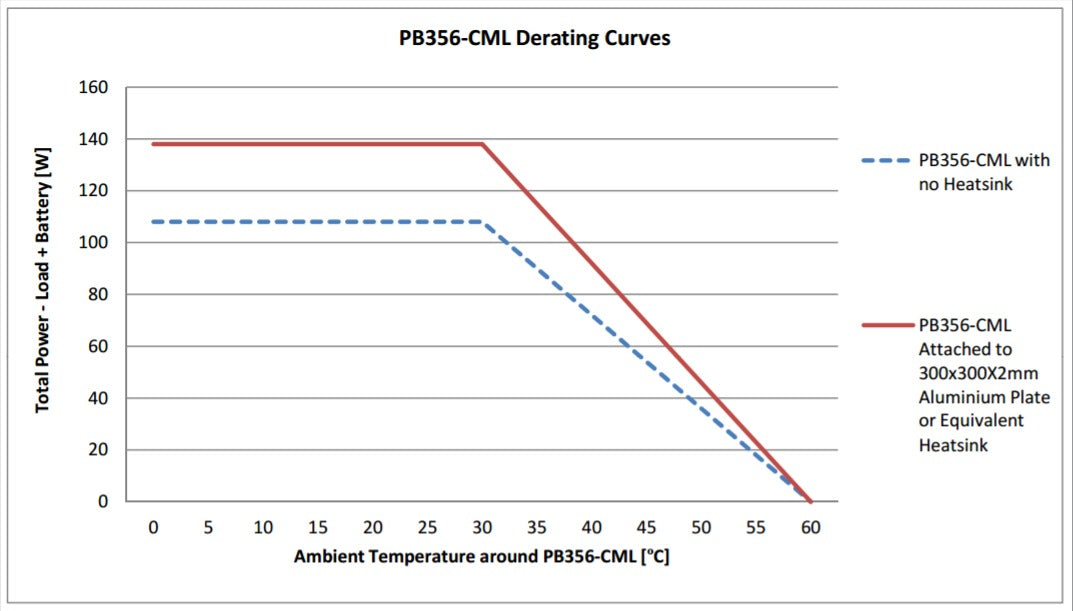
| Operating temperature | 0 to 60°C with derating Refer to derating curve |
| Humidity | 5 to 90% RH non-condensing |
| Over-temperature protection | Automatic & auto-resetting Rectifier max, temp. limiter |
| Cooling requirement | Natural convection |
| MECHANICAL | |
|---|---|
| Input Connector | AC Mains 10A Class 1 IEC60320 power inlet |
| Output and Battery Connector | 4 way pluggable screw terminal block. Suitable for up to 1.5mm² wire |
| Alarms Connector | 16 way pluggable screw terminal block Suitable for up to 1.5mm² wire |
| Case size | 235 L x 93 W x 46 H (mm) |
| Weight | 900g |
| Security Cabinet | View WMBB-C-S Security Cabinet |
Selection Table
| Model Number | Output Voltage | Rated Total Output Current¹ | Maximum Load Current | Battery Charging Current Limit | Output Power | Notes |
|---|---|---|---|---|---|---|
| PB356-12CML | 13.8Vdc | 8A | 8A | 0.5 to 8A Setpoint = 2.0A |
110W | No heatsink |
| 10A | 10A | 0.5 to 10A Setpoint = 2.0A |
138W | Attached to 300 x 300 x 2mm A1 plate |
||
| PB356-24CML | 27.6Vdc | 4A | 4A | 0.5 to 4A Setpoint 1.0A |
110W | No heatsink |
| 5A | 5A | 0.5 to 5A Setpoint 1.0A |
138W | Attached to 300 x 300 x 2mm A1 plate |
¹ Rated Total Output Current = sum of load and battery charging current.
Technical Drawings

Warranty & Returns
Warranty periods vary by product. Please refer to the Powerbox Warranty Policy for the applicable coverage period against manufacturing defects from date of purchase. For returns and RMA requests, please visit our RMA support page or contact our support team directly.
FAQs
Related Products

- All-in-One DC-UPS / Battery Charger
- 13.8Vdc (16/20A) & 27.6Vdc (11-12A) Models
- Chassis Mounting Type

- All-in-One DC-UPS / Battery Charger
- 13.8Vdc (20A) & 27.6Vdc (12A) Models
- 19” Rackmounting – 2RU Height

- All-in-One DC-UPS / Battery Charger
- 13.8Vdc (8A) & 27.6Vdc (4A) Models
- Chassis Mount with Alarm Relays

- 636 - 1056W
- PSU for Battery Backup
- DC UPS Connectable
- Rack Mount
- Constant Float Voltage & Current Limit
- CCT Breakers
- Alarm Relays
- independent Battery Charging Output
- DC OK & Battery OK Alarms
- Battery LVD

- Smart DIN-Mount All-In-One DC-UPS / Charger
- 13.8Vdc, 27.6Vdc or 55.2Vdc Models (138W)
- High Temp. Operation, Battery Testing, Ethernet & Alarms

- High-efficiency, convection-cooled DC-UPS with battery backup.
- Available in 13.8Vdc (3.25A / 6A) and 27.6Vdc (3.0A).
- Complies with AS/NZS 61558.2.16 and EESS approved.

- 50W - 150W
- 12V & 24V Power Supply
- Aluminium Enclosure
- Over current protection
- Over voltage protection
- Over temp protection