Delta Electronics LYTE II DRL 120W Series AC/DC Power Supply
Delta's LYTE II DRL 120W Series DIN rail power supply is engineered for superior performance in industrial environments. It operates efficiently across a wide temperature range from -30°C to +70°C with a cold start capability of -40°C. Featuring universal AC input and a built-in constant current circuit, it handles reactive loads adeptly. This m...
Read MoreDelta's LYTE II DRL 120W Series DIN rail power supply is engineered for superior performance in industrial environments. It operates efficiently across a wide temperature range from -30°C to +70°C with a cold start capability of -40°C. Featuring universal AC input and a built-in constant current circuit, it handles reactive loads adeptly. This model is known for its high power density and reduced no-load power consumption, meeting stringent DOE VI energy standards and compliance with SEMI F47 at 200Vac.
Show Less
Features
- Universal AC input voltage range
- Built-in constant current circuit for reactive loads
- High power density
- Operate from -30°C to +70°C with -40°C Cold Start
- Reduced no-load power consumption
- Compliance with DOE VI Energy Standard
- Compliance to SEMI F47 @ 200Vac
Specifications
| INPUT RATINGS/CHARACTERISTICS | |||
|---|---|---|---|
| Model Number | DRL-12V120W1EN | DRL-24V120W1EN | DRL-48V120W1EN |
| Nominal Input Voltage | 100-240 Vac | ||
| Input Voltage Range | 90-264 Vac | ||
| Nominal Input Frequency | 50-60 Hz | ||
| Input Frequency Range | 47-63 Hz | ||
| Input Current | 2.1 A typ. @ 115 Vac, 1.3 A typ. @ 230 Vac | ||
| Efficiency at 100% Load | 86% typ. @ 230 Vac | 88.5% typ. @ 230 Vac | 89.5% typ. @ 230 Vac |
| Average Efficiency (25%, 50%, 75%, 100%) |
88% typ. @ 115 Vac | 88% typ. @ 115 Vac | 88% typ. @ 115 Vac |
| No Load Power Consumption | 0.15 W max @ 115 Vac & 230 Vac | 0.21 W max @ 115 Vac & 230 Vac | |
| Max Inrush Current (Cold Start) | 35 A typ. @ 230 Vac | ||
| Leakage Current | < 0.5 mA @ 240 Vac | ||
| OUTPUT RATINGS/CHARACTISTICS | |||
|---|---|---|---|
| Model Number | DRL-12V120W1EN | DRL-24V120W1EN | DRL-48V120W1EN |
| Nominal Output Voltage | 12 Vdc | 24 Vdc | 48 Vdc |
| Factory Set Point Tolerance | 12 Vdc ± 1% | 24 Vdc ± 1% | 48 Vdc ± 1% |
| Output Voltage Adjustment Range | 10.8-13.2 Vdc | 21.6-26.4 Vdc | 43.2-52.8 Vdc |
| Output Current | 10.0 A | 5.0 A | 2.5 A |
| Output Power | 120 W max | ||
| Line Regulation | ± 0.5% @ 115 Vac & 230 Vac | ||
| Load Regulation | ± 1.0% | ± 0.5% | ± 0.5% |
| PARD (20MHz) | < 120mVpp @ 0°C to +70°C < 360mVpp @ -30°C to 0°C |
< 150mVpp @ 0°C to+70°C < 450mVpp @ -30°C to 0°C |
< 200mVpp @ 0°C to+70°C < 600mVpp @ -30°C to 0°C |
| Rise Time | 30 ms typ. @ 115 Vac & 230 Vac | ||
| Start-up Time | 500 ms typ. @ 115 Vac & 230 Vac | ||
| Hold-up Time | 10 ms typ. @ 115 Vac (100% load) 16 ms typ. @ 230 Vac (100% load) |
||
| Dynamic Response (Overshoot & Undershoot O/P Voltage) | ± 10% @ 115 Vac & 230 Vac input, 10-100% load (Slew Rate: 2.5 A/μs, 50% duty cycle @ 5 Hz & 10 kHz) |
||
| Start-up with Capacitive Loads | 8,000 μF Max | 8,000 μF Max | 3,000 μF Max |
| MECHANICAL | |||||
|---|---|---|---|---|---|
| Model Number | DRL-12V120W1EN | DRL-24V120W1EN | DRL-48V120W1EN | ||
| Case Cover / Chassis | SGCC / Aluminum | ||||
| Dimensions (H x W x D) | 123.6 x 30 x 116.8 mm (4.87 x 1.57 x 4.60 inch) | ||||
| Unit Weight | 0.45 kg (0.99 lb) | ||||
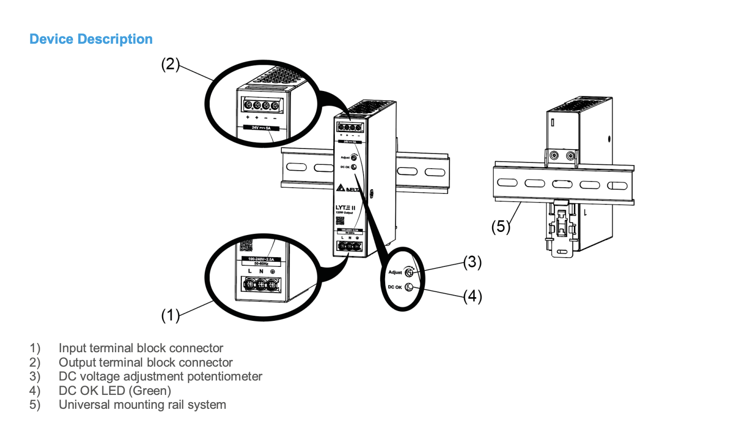
| Indicator | Green LED (DC OK) | ||||
| Cooling System | Convection | ||||
| Terminal | Input | 3 Pins (Rated 300 V/30A) | |||
| Output | 4 Pins (Rated 300 V / 20 A) | ||||
| Wire | Input | AWG 18-12 (Current rating can refer to “AWG Wire Table”) | |||
| Output | AWG 18-12 (Current rating can refer to “AWG Wire Table”) | ||||
| Mounting Rail | Standard TS35 DIN Rail in accordance with EN 60715 | ||||
| Noise (1 Meter from power supply) | Sound Pressure Level (SPL) < 25 dBA | ||||
| ENVIRONMENT | ||||
|---|---|---|---|---|
| Model Number | DRL-12V120W1EN | DRL-24V120W1EN | DRL-48V120W1EN | |
| Surrounding Air Temperature | Operating | -30°C to +70°C (-40°C Cold Start) | ||
| Storage | -40°C to +85°C | |||
| Power De-rating | Temperature | > 40°C de-rate power by 1.67 % / °C @ 115 Vac > 50°C de-rate power by 2.5 % / °C @ 230 Vac |
||
| Input Voltage | < 100 Vac de-rate power by 1% / Vac | |||
| Operating Humidity | 20 to 90% RH (Non-Condensing) | |||
| Operating Altitude | 0 to 5,000 Meters (16,400 ft.) | |||
| Shock Test | Non- Operating | IEC 60068-2-27, Half Sine Wave: 50 G for duration of 11 ms; 3 times per direction, 9 times in total | ||
| Operating | IEC 60068-2-27, Half Sine Wave: 10 G for duration of 11 ms; 1 time in X axis | |||
| Vibration | Non- Operating | IEC 60068-2-6, Random: 5 Hz to 500 Hz (2.09 G); 20 min per axis for all X, Y, Z direction |
||
| Operating | IEC 60068-2-6, Sine Wave: 10 Hz to 500 Hz @ 19.6 m/s2 (2 G peak); 10 min per cycle, 60 min for X direction |
|||
| Over Voltage Protection | II (Compliance to EN 62477-1 OVC III with 2000 meters altitude) | |||
| Pollution Degree | 2 | |||
| PROTECTIONS | |||
|---|---|---|---|
| Model Number | DRL-12V120W1EN | DRL-24V120W1EN | DRL-48V120W1EN |
| Overvoltage | < 17.4 V, SELV Output, Latch Mode | < 33.6 V, SELV Output, Latch Mode | < 64.8 V, SELV Output, Latch Mode |
| Overload / Overcurrent | 105 - 150% of rated load current, Auto-recovery Continuous current limit Mode (Vo > 80%) |
||
| Over Temperature | Latch Mode | ||
| Short Circuit | Hiccup Mode, Non-Latching (Auto-Recovery when the fault is removed) |
||
| Protection Against Shock | Class I with PE connection | ||
| RELIABILITY DATA | ||
|---|---|---|
| MTBF | Telcordia SR-332 |
> 700,000 hrs I/P: 115 Vac & 230 Vac, O/P: 100% load, Ta: 25°C |
| Expected Cap Life Time | 10 years (230 Vac, 50% load @ 40°C) |
|
| SAFETY STANDARDS/DIRECTIVES | ||
|---|---|---|
| Electrical Safety | CB scheme | IEC 62368-1, IEC 60950-1, IEC 61010-1 & -2-201 |
| TUV Bauart | EN 62368-1, EN 61010-1 & -2-201 | |
| UL/cUL | UL 62368-1 | |
| BSMI | CNS14336-1 | |
| EAC | TP TC 004/2011 | |
| KC | K 60950-1 (24 V model only) | |
| CE | In conformance with EMC Directive 2014/30/EU and Low Voltage Directive 2014/35/EU | |
| UKCA | In conformance with Electrical Equipment (Safety) Regulations 2016 and Electromagnetic Compatibility Regulations 2016 | |
| Galvanic Isolation | Input to Output | 3.0 KVac |
| Input to Ground | 2.0 KVac | |
| Input to Ground | 1.0 KVac | |
| EMC | ||||
|---|---|---|---|---|
| Emissions (CE & RE) | CISPR 32, EN/BS EN 55032, EN/BS EN 61000-6-4, AS/NZS CISPR32, EN/BS EN 61204-3, KN 32 (24 V model only) Compliance to FCC Title 47, EN/BS EN 61000-6-3: Class B | |||
| Component Power Supply for General Use |
EN/BS EN 61204-3 | |||
| Immunity | EN/BS EN 55035, KN 35 (24 V model only), EN/BS EN 61000-6-2 Compliance to EN/BS EN 61000-6-1 |
|||
| ElectrostaticDischarge | IEC 61000-4-2 | Level 4 Criteria A Air Discharge: 15 kV Contact Discharge: 8 kV |
||
| Radiated Field | IEC 61000-4-3 | Criteria A 80 MHz – 1 GHz, 10 V/M, 80% Modulation (1 kHz) 1.4 GHz – 2 GHz, 3 V/M, 80% Modulation (1 kHz) 2 GHz – 2.7 GHz, 1 V/M, 80% Modulation (1 kHz) |
||
| Electrical Fast Transient / Burst | IEC 61000-4-4 | Level 3 Criteria A 2kV | ||
| Surge | IEC 61000-4-5 | Level 4 Criteria A Common Mode: 4 kV Differential Mode: 2 kV |
||
| Conducted | IEC 61000-4-6 | Level 3 Criteria A 150 kHz – 80 MHz, 10 Vrms |
||
| Power Frequency Magnetic Fields | IEC 61000-4-8 | Level 4 Criteria A 30 A/m |
||
| Voltage Dips and Interruptions | IEC 61000-4-11 | 0% residual; 1 cycle, Criteria B 40% residual; 10 cycle, Criteria C 70% residual; 25 cycle, Criteria C |
||
| Harmonic Current Emission | IEC/EN/BS EN 61000-3-2, Class A | |||
| Voltage Fluctuation and Flicker | IEC/EN/BS EN 61000-3-3 | |||
| Voltage Sag Immunity SEMI F47 – 0706 | 80% of 200 Vac 70% of 200 Vac 50% of 200 Vac |
160 Vac, 1000 ms 140 Vac, 500 ms 100 Vac, 200 ms |
Criteria A Criteria A Criteria A |
|
Selection Table
| MODEL NUMBER | INPUT VOLTAGE RANGE | RATED OUTPUT VOLTAGE | RATED OUTPUT CURRENT |
|---|---|---|---|
| DRL-12V120W1EN | 90-264 Vac | 12 Vdc | 10.0 A |
| DRL-24V120W1EN | 24 Vdc | 5.0 A | |
| DRL-48V120W1EN | 48 Vdc | 2.5 A |
Technical Drawings

Warranty & Returns
Warranty periods vary by product. Please refer to the Powerbox Warranty Policy for the applicable coverage period against manufacturing defects from date of purchase. For returns and RMA requests, please visit our RMA support page or contact our support team directly.
Related Products

- Universal AC input voltage range
- Built-in constant current circuit for reactive loads
- High power density
- Operate from -30°C to +70°C with -40°C Cold Start
- Slim type design
- Reduced no-load power consumption
- Compliance to SEMI F47 @ 200 Vac

- Universal AC input voltage range
- Built-in constant current circuit for reactive loads
- High power density
- Operate from -30°C to +70°C with -40°C Cold Start
- Slim type design
- Reduced no-load power consumption
- Compliance to SEMI F47 @ 200 Vac

- 120W output power
- 12/24/48 Vdc output voltages
- Universal AC input voltage range

- 240W output power
- 12/24/48 Vdc output voltages
- Universal AC input voltage range

- 480W output power
- 24/48 Vdc output voltages
- Universal AC input voltage range

- 24V/48V 20A & 40A
- Redundancy module
- DIN Rail mounting
- 2 Channel Inputs
- 2 x DC OK signal
- Voltage alarms
- Wide Input 22-60Vdc
- RoHS Compliant
- Conformal coating
- Corrosion resistant