
Victron SmartSolar MPPT 250/60 to 250/100 VE.Can Charge Controller
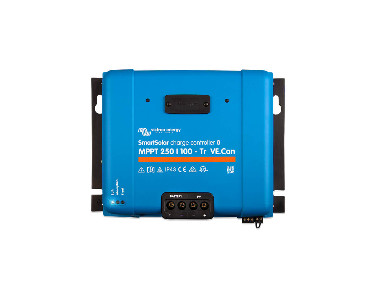
The Victron SmartSolar MPPT 250 VE.Can range covers four solar charge controllers, the 250/60, 250/70, 250/85 and 250/100, for PV arrays up to 250V open circuit voltage. The second number in each model name is the maximum charge current: 60A, 70A, 85A or 100A. Battery voltage is selected automatically at 12V, 24V or 48V, with 36V available thro...
Read MoreThe Victron SmartSolar MPPT 250 VE.Can range covers four solar charge controllers, the 250/60, 250/70, 250/85 and 250/100, for PV arrays up to 250V open circuit voltage. The second number in each model name is the maximum charge current: 60A, 70A, 85A or 100A.
Battery voltage is selected automatically at 12V, 24V or 48V, with 36V available through manual configuration. At 48V, nominal PV power runs from about 4000W on the 250/70 to 5800W on the 250/100. Peak conversion efficiency is up to 99%, and the tracking algorithm scans the full PV curve to find the true maximum power point when part of the array is shaded.
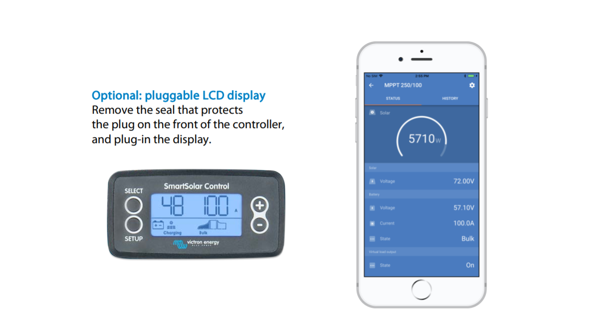
Every Victron SmartSolar MPPT 250 VE.Can unit has three communication options: built-in Bluetooth for setup and monitoring in the VictronConnect app, a VE.Direct port, and a VE.Can port for connection to a GX device or CAN network. Over VE.Can, up to 25 controllers can be synchronised in parallel to charge a shared battery bank, or up to 10 over Bluetooth. A pluggable LCD display is available as an option.
Protection covers PV reverse polarity, fused battery reverse polarity, output short circuit and over-temperature. The enclosure is rated IP43 for the electronics and IP22 at the connection area, with an operating range of -30°C to +60°C and full rated output up to 40°C. A programmable relay and remote on/off connector are standard, and the series complies with EN/IEC 62109-1, UL 1741 and CSA C22.2.
Typical applications include off-grid and hybrid systems, remote telecom and monitoring sites, and commercial or industrial installations that need more charge current than a single controller can deliver. Powerbox Australia's engineering team can help with PV string sizing, parallel configurations and battery integration for the Victron SmartSolar MPPT 250 series.
Show Less
Features
- Ultra-Fast MPPT Technology: Enhances energy capture by up to 30% compared to PWM controllers, especially under dynamic light conditions.
- Partial Shading Optimisation: Advanced algorithms ensure maximum power point detection for optimal energy harvest even in shaded environments.
- High Conversion Efficiency: With a peak efficiency exceeding 99%, it ensures minimal energy loss during conversion.
- Bluetooth Smart Integration: Easily monitor and configure your charge controller wirelessly via the VictronConnect app.
- VE.Can and VE.Direct Connectivity: Simple integration with GX devices for real-time monitoring and system management.
- Advanced Maximum Power Point Detection in case of partial shading
- Robust Protection: Comprehensive safeguards against PV short circuits, reverse polarity, over-temperature, and more.
- Parallel Charging Capability: Synchronise up to 25 units using VE.Can or 10 units via Bluetooth for larger systems.
- Fully Programmable Charge Algorithms: Customise charging profiles or select from eight pre-configured options for diverse battery types.
- Versatile Application Range: Supports 12V, 24V, and 48V systems with auto-selection, accommodating various solar setups.
Specifications
| SMARTSOLAR CHARGE CONTROLLER | |||||||||||||||||||||||||||||||||||||||||||||||||
|---|---|---|---|---|---|---|---|---|---|---|---|---|---|---|---|---|---|---|---|---|---|---|---|---|---|---|---|---|---|---|---|---|---|---|---|---|---|---|---|---|---|---|---|---|---|---|---|---|---|
| Battery Voltage |
12V, 24V, 36V, 48V Auto Select (software tool needed to select 36V) See selection table |
||||||||||||||||||||||||||||||||||||||||||||||||
| Rated charge current |
See selection table |
||||||||||||||||||||||||||||||||||||||||||||||||
| Nominal PV power |
See selection table |
||||||||||||||||||||||||||||||||||||||||||||||||
| Max PV open circuit voltage |
250V absolute max coldest conditions 245V start-up and operating max |
||||||||||||||||||||||||||||||||||||||||||||||||
| Maximum efficiency |
99% |
||||||||||||||||||||||||||||||||||||||||||||||||
| Self-consumption |
Less than 35mA @ 12V / 20mA @ 48V |
||||||||||||||||||||||||||||||||||||||||||||||||
| Charge voltage 'absorption' |
Default setting: 14,4 / 28,8 / 43,2 / 57,6V (adjustable with: rotary switch, display, VE.Direct or Bluetooth) |
||||||||||||||||||||||||||||||||||||||||||||||||
| Charge voltage 'float' |
Default setting: 13,8 / 27,6 / 41,4 / 55,2V (adjustable with: rotary switch, display, VE.Direct or Bluetooth) |
||||||||||||||||||||||||||||||||||||||||||||||||
| Charge algorithm |
multi-stage adaptive |
||||||||||||||||||||||||||||||||||||||||||||||||
| Temperature compensation |
12V: -16 mV / 24V: -32 mV / 48V: -64 mV/°C |
||||||||||||||||||||||||||||||||||||||||||||||||
| Protection |
Battery reverse polarity (fuse, not user accessible)
PV reverse polarity Output short circuit Over temperature |
||||||||||||||||||||||||||||||||||||||||||||||||
| Operating temperature |
-30 to +60°C (full rated output up to 40°C) |
||||||||||||||||||||||||||||||||||||||||||||||||
| Humidity |
95%, non-condensing |
||||||||||||||||||||||||||||||||||||||||||||||||
| Data communication port |
VE.Direct or Bluetooth |
||||||||||||||||||||||||||||||||||||||||||||||||
| Remote on/off |
Yes (2 pole connector) |
||||||||||||||||||||||||||||||||||||||||||||||||
| Programmable relay |
DPST AC rating: 240VAC / 4A DC rating: 4A up to 35VDC, 1A up to 60VDC |
||||||||||||||||||||||||||||||||||||||||||||||||
| Parallel operation |
Yes (not synchronized) |
||||||||||||||||||||||||||||||||||||||||||||||||
| STANDARDS | |||||||||||||||||||||||||||||||||||||||||||||||||
|---|---|---|---|---|---|---|---|---|---|---|---|---|---|---|---|---|---|---|---|---|---|---|---|---|---|---|---|---|---|---|---|---|---|---|---|---|---|---|---|---|---|---|---|---|---|---|---|---|---|
| Safety | EN/IEC 62109-1, UL 1741, CSA C22.2 | ||||||||||||||||||||||||||||||||||||||||||||||||
| MECHANICAL | |||||||||||||||||||||||||||||||||||||||||||||||||
|---|---|---|---|---|---|---|---|---|---|---|---|---|---|---|---|---|---|---|---|---|---|---|---|---|---|---|---|---|---|---|---|---|---|---|---|---|---|---|---|---|---|---|---|---|---|---|---|---|---|
| Colour | Blue (RAL 5012) | ||||||||||||||||||||||||||||||||||||||||||||||||
| PV terminals |
35 mm² / AWG2 (Tr models) Two sets of MC4 connectors (MC4 models 250/60 and 250/70) . Three sets of MC4 connectors (MC4 models 250/85 and 250/100) . MC4 models: several splitter pairs may be needed to parallel the strings of solar panels. Maximum current per MC4 connector: 30A (the MC4 connectors are parallel connected to one MPPT tracker) |
||||||||||||||||||||||||||||||||||||||||||||||||
| Battery terminals | 35 mm² / AWG2 | ||||||||||||||||||||||||||||||||||||||||||||||||
| Protection category | IP43 (electronic components),
IP22 (connection area) |
||||||||||||||||||||||||||||||||||||||||||||||||
| Weight |
MPPT250/60-70, 3 kg MPPT250/85-100, 4,5 kg |
||||||||||||||||||||||||||||||||||||||||||||||||
|
Dimensions (h.w.d)mm MPPT250/60-70 |
Tr models: 185 x 250 x 95 MC4 models: 215 x 250 x 95 |
||||||||||||||||||||||||||||||||||||||||||||||||
|
Dimensions (h.w.d)mm MPPT250/85-100 |
Tr models: 216 x 295 x 103 MC4 models: 246 x 295 x 103 |
||||||||||||||||||||||||||||||||||||||||||||||||
Selection Table
|
SmartSolar Tr/MC4 Connector |
MPPT 250/70 |
MPPT 250/85 |
MPPT 250/100 |
|---|---|---|---|
|
Battery voltage |
12 / 24 / 48V Auto Select |
12 / 24 / 48V Auto Select |
12 / 24 / 48V Auto Select |
| Rated charge current | 70A | 85A | 100A |
| Nominal PV power, 12V 1a,b) | 1000W | 1200W | 1450W |
| Nominal PV power, 24V 1a,b) | 2000W | 2400W | 2900W |
| Nominal PV power, 48V 1a,b) | 4000W | 4900W | 5800W |
| Max. PV short circuit current 2) | 35A (max 30A per MC4) | 70A (max 30A per MC4) | 70A (max 30A per MC4) |
1a) If more PV power is connected, the controller will limit input power to the stated maximum.
1b) The PV voltage must exceed Vbat + 5V for the controller to start. Thereafter the minimum PV voltage is Vbat + 1V.
2) A PV array with a higher short circuit current may damage the controller in case of reverse polarity connection of the PV array.
Technical Drawings
Warranty & Returns
Warranty periods vary by product. Please refer to the Powerbox Warranty Policy for the applicable coverage period against manufacturing defects from date of purchase. For returns and RMA requests, please visit our RMA support page or contact our support team directly.
FAQs
Related Products


- 45A~ 100A
- 12V~48Vdc
- Max PV 150V

- Ultra-Fast MPPT Technology
- Battery Life Algorithm
- Bluetooth Smart Integration
- VE.Direct Communication
- Load Output with Over-Discharge Protection
- Adaptive Charging Algorithms
- Compact and Robust Design
- Durable Protection