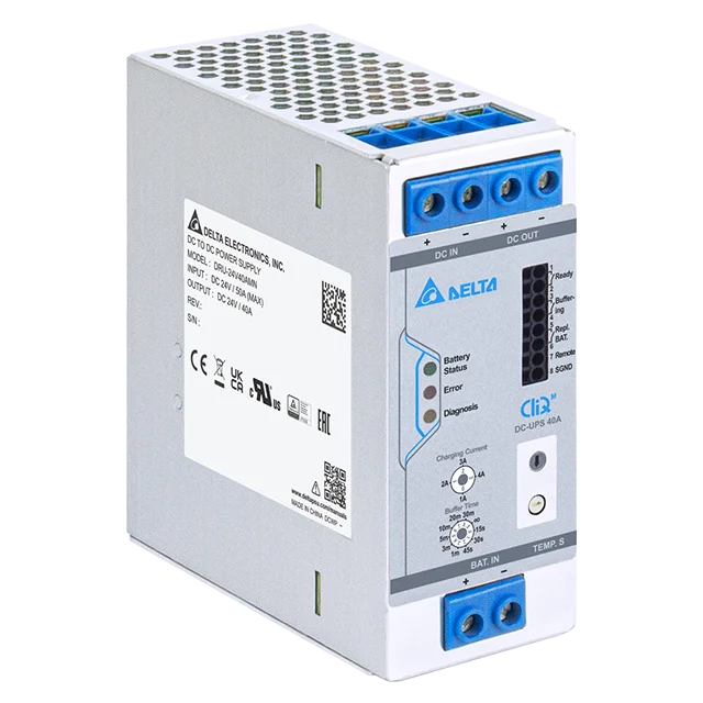
Delta Electronics CliQ M DRU-24VAMN Series DC UPS Module
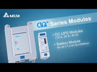
The Delta Electronics CliQ M DRU-24V AMN DC UPS range provides a reliable and efficient backup solution for maintaining uninterrupted 24 V DC power in industrial, automation, utility, water telemetry, and communication systems. Available in 10 A, 20 A, and 40 A output variants, the series combines high efficiency, intelligent battery management,...
Read MoreThe Delta Electronics CliQ M DRU-24V AMN DC UPS range provides a reliable and efficient backup solution for maintaining uninterrupted 24 V DC power in industrial, automation, utility, water telemetry, and communication systems. Available in 10 A, 20 A, and 40 A output variants, the series combines high efficiency, intelligent battery management, and robust electrical protection within a compact, corrosion-resistant aluminium enclosure engineered for long-term field deployment. All models operate from a wide 18–30 V DC input range and deliver stable regulated output at Vout = Vin minus 0.5 V during normal operation, ensuring dependable support for sensitive loads.
Each model features a 150 percent power boost capability for up to seven seconds, allowing the UPS to handle inrush currents and short transient demands without system disruption. When the input supply is lost, the units automatically transition into battery mode, delivering uninterrupted output power at Vbattery minus 0.5 V. Adjustable charging current and selectable buffering time give integrators the flexibility to pair the UPS with a broad range of sealed lead-acid battery capacities, while battery temperature sensing and over-discharge protection help extend battery lifespan and maintain predictable performance. These features, combined with high 98 percent efficiency across the series, support energy-conscious designs and reduce system heating.
The DRU-24V AMN range incorporates clear operational visibility through intuitive LED indicators and dedicated relay contacts for Ready, Buffering, and Replace Battery conditions. This diagnostic structure provides quick status identification during installation, routine inspection, or remote system monitoring. Integrated protections operate continuously, including input undervoltage shutdown, reverse polarity protection, deep discharge protection around 21 V, thermal shutdown when operating conditions exceed recommended limits, and safeguards against incorrect battery voltage. These protective layers enhance system resilience and reduce maintenance intervention across diverse application environments.
Designed for demanding conditions, all models operate reliably across a wide temperature range from –40 °C to +70 °C, with de-rating applied above 60 °C as indicated in the datasheet’s thermal performance guidelines. Long-term reliability is supported by an MTBF rating above 500,000 hours, and installation is simplified through TS35 DIN rail mounting and consistent mechanical design between the 10 A and 20 A models, with a slightly wider form factor for the 40 A variant. With robust electrical performance, intelligent battery control, and a compact form suited to modern control panels, the CliQ M DRU-24V AMN DC UPS series provides a dependable backup solution for maintaining power continuity in any 24 V DC system.
Show Less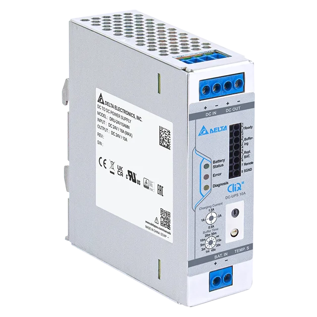
Features
- Intelligent Battery Management for Extended Service Life - The CliQ M DC-UPS range incorporates advanced charge control and temperature-based supervision that help maximise the lifespan of connected sealed lead-acid batteries. Each model monitors battery conditions continuously, adjusting charge current automatically when input voltage falls below 24 V, and halting charging entirely when temperatures move outside the recommended thresholds. This level of intelligence reduces stress on the battery across changing environmental conditions and ensures stable readiness for backup events. Protection against deep discharge at approximately 21 V further prevents irreversible battery damage, making the system more resilient during extended outages.
- Power Continuity During Input Loss - All models in the series are engineered to deliver uninterrupted 24 V power during supply interruptions, ensuring that critical automation, signalling, telemetry, and communication loads continue operating without reset or data loss. When the DC input drops away, the UPS transitions smoothly into battery mode with output delivered at Vbattery minus 0.5 V. This seamless handover, free from switching delays or output instability, is critical for equipment that must remain continuously energised, particularly in remote or unmanned installations.
- High Inrush Handling Through Short-Duration Power Boost - A defining capability of the 10 A, 20 A, and 40 A variants is their built-in short-term power boost function, which provides 150 percent of rated output for up to seven seconds. This allows each UPS to absorb inrush currents associated with motors, solenoids, relays, and other inductive loads without nuisance shutdowns. The ability to withstand momentary surges helps reduce system design constraints and ensures a more stable startup profile for connected equipment, even under fluctuating load conditions.
- Comprehensive Diagnostics Through Relay Contacts and LED Indicators - Maintenance teams benefit from immediate insight into system status through clearly defined relay outputs and diagnostic LEDs. The UPS communicates key states such as Battery Ready, Buffering, and Replace Battery, while LED indicators provide real-time feedback on charge level, fault conditions, polarity issues, and temperature warnings. These diagnostics enable rapid fault identification, simplify commissioning, and provide valuable integration points for remote monitoring systems such as PLCs, RTUs, SCADA platforms, and building management systems.
- Robust Electrical and Environmental Protection for Demanding Sites - Each model in the CliQ M range includes a suite of protective mechanisms designed to safeguard both the UPS and downstream equipment. This includes reverse polarity protection on the battery terminals, incorrect battery voltage detection up to 30 V, overvoltage shutdown on the input side, and automatic recovery once normal conditions return. Temperature-driven shutdown prevents overheating during prolonged high-load operation, while vibration and shock ratings defined in the datasheet ensure stable performance in industrial environments. Together, these protections support long-term reliability in harsh, high-duty applications.
- Compact DIN Rail Design That Simplifies Panel Integration - The unified mechanical design across the 10 A and 20 A models, and the slightly wider footprint of the 40 A variant, ensures easy installation within new and existing control cabinets. All units mount on standard TS35 DIN rail and require minimal clearance for natural convection cooling, making them well-suited to modern panel layouts where space is at a premium. With no active cooling elements and minimal service requirements, the UPS modules provide a low-maintenance backup solution that supports clean cable routing, straightforward commissioning, and long-term operational stability.
Specifications
| INPUT RATINGS/CHARACTERISTICS | |||
|---|---|---|---|
| Model Number | DRU-24V10AMN | DRU-24V20AMN | DRU-24V40AMN |
| Nominal Input Voltage | 240Vdc | ||
| Input Voltage Range | 18-30Vdc | ||
| Efficiency (Normal Operation)*1 | 98% typ. | ||
| *1 Vin = 24 Vdc, Iout = Max rated output current and battery full charged | |||
| OUTPUT RATINGS/CHARACTERISTICS (NORMAL OPERATION) | ||||
|---|---|---|---|---|
| Model Number |
DRU-24V10AMN | DRU-24V20AMN | DRU-24V40AMN | |
| Output Voltage Range | Vout = Vin - 0.5 Vdc (17.5 – 29.5 Vdc) | |||
| Rated Output Current |
Max. |
10.0 A 15.0 A (7 s typ.)*2 |
20.0 A 30.0 A (7 s typ.)*2 |
40.0 A 60.0 A (7 s typ.)*2 |
| Output Power | Max. Max. |
240 W 360 W (7 s typ.)*2 |
480 W 720 W (7 s typ.)*2 |
960 W 1440 W (7 s typ.)*2 |
| Power Boost Duration | Typ. | 7 seconds | Power Boost for 7 seconds at output voltage range | |
| Power Boost Recovery Time |
Typ. | 5 seconds | If the Power Boost is over 7 seconds, it will trigger the overload protection and the DC-UPS module will turn off. After 5 seconds, the DC-UPS module will turn on automatically. | |
| *2 Supports Power Boost for 7 seconds at 24 Vdc, AC DC power supply also need to have Power Boost function. | ||||
| BATTERY & BUFFERING CHARACTERISTICS | |||||||
|---|---|---|---|---|---|---|---|
| Model Number |
DRU-24V10AM | DRU-24V20AMN |
DRU-24V40AMN |
||||
| Nominal Battery Voltage | 24 Vdc, SLA Sealed lead acid battery 2 x 12 Vdc, SLA Sealed lead acid battery in series |
||||||
| Battery Discharging Voltage Range | 21 Vdc ... 27.6 Vdc 30 Vdc Max (the maximum voltage that will not cause damage to the unit) |
||||||
| Output Voltage Range (Battery Operation) | Vout = VBattery - 0.5 Vdc | ||||||
| Battery Capacity*3 | 3.4 AH ~ 100 AH | ||||||
| Battery Charging Current*4 | 0.5 A, 1 A, 1.5 A, 2 A (typ.) (constant current) |
0.75 A, 1.5 A, 2.25 A, 3 A (typ.) (constant current) | 1 A, 2 A, 3 A, 4 A (typ.) (constant current) |
||||
| Scale (White Switch) |
Charging Current |
Scale (White Switch) |
Charging Current |
Scale (White Switch) |
Charging Current |
||
| 0 | 0.5A | 0 | 0.75A | 0 | 1A | ||
| 1 | 1A | 1 | 1.5A | 1 | 2A | ||
| 2 | 1.5A | 2 | 2.25A | 2 | 3A | ||
| 3 | 2A | 3 | 3A | 3 | 4A | ||
| Charging Time | < 9 hr ± 1 hr (2 A charging current for 24 V/12 AH battery) |
< 6 hr ± 1 hr (3 A charging current for 24 V/12 AH battery) |
< 4.5 hr ± 1 hr (4 A charging current for 24 V/12 AH battery) |
||||
| Buffering Time | 15s, 30s, 45s, 1m, 3m, 5m, 10m, 20m, 30m, ∞ | ||||||
| Scale (Blue Switch) |
Buffering Time | ||||||
| 0 | 15s | ||||||
| 1 | 30s | ||||||
| 2 | 45s | ||||||
| 3 | 1m | ||||||
| 4 | 3m | ||||||
| 5 | 5m | ||||||
| 6 | 10m | ||||||
| 7 | 20m | ||||||
| 8 | 30m | ||||||
| 9 | ∞ | ||||||
| End-of-Charge Voltage | 27.6 V | ||||||
| Battery Current Consumption*5 | < 200 mA | ||||||
| *3 Do not short battery + and - together to prevent battery explosion. Please add an external overcurrent protective device between the battery and product (BAT.IN connector) to prevent the battery from short-circuiting. Ensure that a suitable charging current is chosen based on the battery’s capability to prevent the battery from overheating. Delta can offer a battery module (DRN-24V7AAEN) for 2 x 12 Vdc / 7.2 AH lead acid battery. The recommended 7.2 AH battery source is Yuasa: NP7-12 & CSB: GP1272F2. *4 The charging current can be adjusted with a four-step rotary selector switch, which will automatically de-rate when Vin < 24 Vdc. *5 Iout = 0 A and without battery charge |
|||||||
| MECHANICAL | ||||
|---|---|---|---|---|
| Model Number |
DRU-24V10AMN | DRU-24V20AMN | DRU-24V40AMN | |
| Case Cover / Chassis | Aluminium | |||
| Dimensions (H x W x D) | 124 x 38 x 117 mm (4.88 x 1.50 x 4.61 inch) |
124 x 50 x 117 mm (4.88 x 1.97 x 4.61 inch) |
||
| Unit Weight | 0.52 kg (1.15 lb) | 0.53 kg (1.17 lb) | 0.66 kg (1.46 lb) | |
| Cooling System | Convection | |||
| Terminal | Input / Output (CN202) |
4 Pins | ||
| Battery (CN203) |
2 Pins | |||
| Signal (CN101) |
8 Pins | |||
| Temperature Sensor & Rx/Tx*6 (CN206) |
4 Pins Power Supply Header: CVILUX CP3504P1H00-NH Mating Connector: CVILUX CP3504S0010 Terminal: CVILUX CP35TN21PES |
|||
| Wire | Input / Output | AWG 18-8 (Load: 0-5 A) | AWG 14-8 (Load: 0-10 A) | AWG 10-6 (Load: 0-20 A) |
| Battery | AWG 14-8 (Load: 5-10 A) | AWG 10-8 (Load: 10-20 A) | AWG 8-6 (Load: 20-40 A) | |
| Signal | AWG 24-12 | |||
| Mounting Rail | Standard TS35 DIN Rail in accordance with EN 60715 | |||
| Noise (1 Meter from power supply) | Sound Pressure Level (SPL) < 40 dBA | |||
| *6 The Rx/Tx function can only be used with the Delta battery module (DRN-24V7AAEN). | ||||
| ENVIRONMENT | ||||
|---|---|---|---|---|
| Model Number |
DRU-24V10AMN | DRU-24V20AMN | DRU-24V40AMN | |
| Surrounding Air Temperature |
Operating | -40°C to +70°C | ||
| Storage | -40°C to +85°C | |||
| Output Power De-rating*7 |
Temperature Normal Operation |
> 60°C de-rate power by 2.5% / °C (battery is fully charged) If the battery is not fully charged at max load, it is recommended that the surrounding air temperature should not exceed 50°C. |
||
| Temperature Battery Operation |
> 60°C de-rate power by 2.5% / °C | |||
| Operating Humidity | 5 to 95% RH (Non-Condensing) | |||
| Operating Altitude | 0 to 6,000 m (Approvals apply only up to 5,000 m) | |||
| Shock Test | Non-Operating | IEC 60068-2-27, 30 G (300 m/s²) for a duration of 18 ms, 1 time per direction, 2 times in total |
||
| Vibration | Non-Operating | IEC 60068-2-6, 10 Hz to 500 Hz @ 30 m/s² (3 G peak); 60 min per axis for all X, Y, Z direction |
||
| Operating Wind Power Application |
EN 60068-2-64 | |||
| Pollution Degree | 2 | |||
| *7 Output power de-rating is for the DC-UPS module only. If it is combined with a battery, please check the battery’s operating temperature specification. | ||||
| PROTECTIONS | ||||
|---|---|---|---|---|
| Model Number |
DRU-24V10AMN | DRU-24V20AMN | DRU-24V40AMN | |
| Overload / Overcurrent / Short (at system) |
Normal Operation |
Auto Recovery | ||
| Battery Operation |
Latch off | |||
| Over Temperature | Normal Operation |
Auto Recovery | ||
| Battery Operation |
Latch off | |||
| Overvoltage | Auto Recovery | |||
| Insufficient Input Voltage Protection | Yes | |||
| Input Polarity Protection | Yes | |||
| Battery Polarity Protection | Yes | |||
| Wrong Battery Voltage Protection | Yes, 30 Vdc Max (the maximum voltage that will not cause damage to the unit) | |||
| Battery Temperature Protection (With Temperature Sensor, CN206 pin1 and pin3)*8 (With Rx/Tx function, CN206 pin2 and pin4)*9 |
Normal Operation |
Battery surrounding air temperature < 0°C or > 40°C, DC-UPS will stop charging to protect battery and extend battery life |
||
| Battery Operation |
Battery surrounding air temperature < -10°C or > 50°C, DC-UPS will stop buffering to protect battery and extend battery life |
|||
| Battery Deep Discharge Protection | Yes (21 V typ.) | |||
| Degree of Protection | IP20 | |||
| Protection Against Shock | Class III | |||
| *8 Users can use an external Negative Temperature Coefficient (NTC) thermistor with 10 kOhm F 3435K ±1% to sense the battery temperature. *9 The Rx/Tx function can only be used with the Delta battery module (DRN-24V7AAEN) to detect battery temperature. |
||||
| RELIABILITY DATA | ||||
|---|---|---|---|---|
| MTBF | > 500,000 hrs. as per Telcordia SR-332 | |||
| SAFETY STANDARDS / DIRECTIVES | ||||
|---|---|---|---|---|
| Model Number |
DRU-24V10AMN | DRU-24V20AMN | DRU-24V40AMN | |
| Electrical Safety | CB scheme | IEC 62368-1 | ||
| TUV Bauart | EN 62368-1 | |||
| UL/cUL recognized |
UL 62368-1 and CAN/CSA C22.2 No. 62368-1 (File No. E131881) | |||
| EAC | TP TC 002/2011 | |||
| CE | In conformance with EMC Directive 2014/30/EU and Low Voltage Directive 2014/35/EU | |||
| UKCA | In conformance with Electromagnetic Compatibility Regulations 2016 and Electrical Equipment (Safety) Regulations 2016 |
|||
| Galvanic Isolation | Power Port to Housing |
500Vac | ||
| Signal Port to Housing |
500Vac | |||
| Power Port to Signal Port |
500Vac | |||
| EMC | ||||
|---|---|---|---|---|
| Model Number |
DRU-24V10AMN | DRU-24V20AMN | DRU-24V40AMN | |
| Emissions (CE & RE) | EN/BS EN 61000-6-4, EN 61204-3 | |||
| Immunity | EN/BS EN 61000-6-2, EN 61204-3 | |||
| Electrostatic Discharge |
IEC 61000-4-2 | Level 4 Criteria A1) Air Discharge: 15 kV Contact Discharge: 8 kV |
||
| Radiated Field | IEC 61000-4-3 | Level 3 Criteria A1) 80 MHz – 1 GHz, 10 V/M, 80% modulation (1 kHz) 1.4 GHz – 2 GHz, 3 V/M, 80% modulation (1 kHz) 2 GHz – 2.7 GHz, 1 V/M, 80% modulation (1 kHz) |
||
| Electrical Fast Transient / Burst |
IEC 61000-4-4 | Level 3 Criteria A1) 2 kV (Input power ports) |
||
| Surge | IEC 61000-4-5 | Criteria A1) 0.5 kV (DC Input) 0.5 kV (DC Output) |
||
| Conducted | IEC 61000-4-6 | Level 3 Criteria A1) 150 kHz – 80 MHz, 10 Vrms |
||
| Power Frequency Magnetic Fields |
IEC 61000-4-8 | Criteria A1) 30 A/Meter |
||
| 1) Criteria A: Normal performance within the specification limits | ||||
Technical Drawings


Warranty & Returns
Warranty periods vary by product. Please refer to the Powerbox Warranty Policy for the applicable coverage period against manufacturing defects from date of purchase. For returns and RMA requests, please visit our RMA support page or contact our support team directly.
Related Products

- 90-264V AC input
- 10W-100W rated in 12V and 24V outputs
- Low Profile design
- Building Automation style
- 24Vdc 80W - 960W
- DIN Rail Mountable
- 150% Power Boost
- Corrosion Resistant
- Aluminium Chassis
- Conformal Coating
- Op Temp -25C to 80C
- MTBF > 500 000hrs
- Industrial Control.

- 24Vdc 80W, 960W
- DIN Rail Mountable
- 150% Power Boost
- Corrosion Resistant
- Aluminium Chassis
- Conformal Coating
- Op Temp -25C to 80C
- MTBF > 500 000hrs
- Industrial Control.

- 24V/48V 20A & 40A
- Redundancy module
- DIN Rail mounting
- 2 Channel Inputs
- 2 x DC OK signal
- Voltage alarms
- Wide Input 22-60Vdc
- RoHS Compliant
- Conformal coating
- Corrosion resistant

- 120W - 240W
- Output 24Vdc - 5A or 10A
- Conformal coating on PCB
- Overvoltage / Overcurrent / Over temperature protection
- 24V/48V 20A & 40A
- Redundancy module
- DIN Rail mounting
- 2 Channel Inputs
- 2 x DC OK signal
- Voltage alarms
- Wide Input 22-60Vdc
- RoHS Compliant
- Conformal coating
- Corrosion resistant

- Universal AC input voltage: 3 x 320Vac – 600Vac (3-Phase) or 2 x 360Vac – 600Vac (2-Phase)
- Power will not de-rate for the entire input voltage range
- Power Boost of 150% for 5 seconds
- Full corrosion resistant aluminium chassis
- Conformal coating on PCBA to protect against chemical and dust pollutants
- 24V/48V 20A & 40A
- Redundancy module
- DIN Rail mounting
- 2 Channel Inputs
- 2 x DC OK signal
- Voltage alarms
- Wide Input 22-60Vdc
- RoHS Compliant
- Conformal coating
- Corrosion resistant

- Reliable design, with expected life of 10 years
- Compact, rugged design for ease of handling and installation
- With Conformal Coating on PCBA (DRP024V120W1BN)
- Class I, Div 2 Hazardous Locations (DRP024V120W1BA)
- IP20 Compliant
- Meets worldwide safety requirements
- RoHS Directive 2011/65/EU Compliant
- Overvoltage / Overcurrent / Over Temperature Protections
- 150% Power Boost (steady state peak load) for 5 seconds

- Worldwide AC input range without power de-rating
- 150% Power Boost (steady state peak load) for 5 seconds
- Full corrosion resistant Aluminium chassis
- Extreme low temperature cold start at -40°C
- Conformal coating on PCBA to protect against chemical and dust pollutants
- Hazardous Locations approval to ATEX and Class I, Div 2 (DRP048V060W1BA)
- Overvoltage / Overcurrent / Over Temperature Protections
- IP20 Compliant

- 24V/48V 20A & 40A
- Redundancy module
- DIN Rail mounting
- 2 Channel Inputs
- 2 x DC OK signal
- Voltage alarms
- Wide Input 22-60Vdc
- RoHS Compliant
- Conformal coating
- Corrosion resistant